
Publications in Associated Project A-X4
- Michalkowski, C., Veyskarami, M., Bringedal, C., Helmig, R., & Schleper, V. (2022). Two-phase Flow Dynamics at the Interface Between GDL and Gas Distributor Channel Using a Pore-Network Model. Transport in Porous Media, 144, Article 2. https://doi.org/10.1007/s11242-022-01813-4
Research
Duration
This project was concluded in the first funding period.
About this project
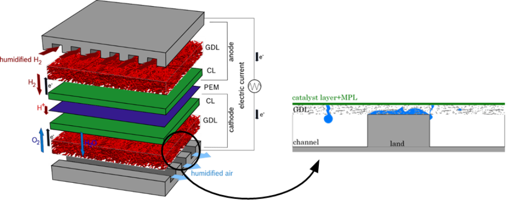
For optimal operating conditions of a polymer electrolyte membrane fuel cell (PEM FC), a sophisticated water management is crucial. Therefore, it is necessary to understand the transport mechanisms of water throughout the cell constituents especially on the cathode where the excess water has to be removed. Microscale modeling of diffusion layers and flow field has been established as a favorable technique to investigate the ongoing processes.
In this research project, the gas diffusion layer and the cathode flow field are considered as a porous medium. For an analysis of the occurring processes on a pore-scale a pore network modeling approach is used. This concept allows a more flexible and more efficient handling of the flow regimes and occurring phenomena than a direct numerical simulation.
Investigating the interface between the porous layers, a particular challenge is the combination and interaction of the different material structures and wetting properties at the interface and its influence on the flow. The PhD project is part of a cooperation with the Robert Bosch GmbH and focusses on the development of a concept to model the interface between the porous layers on the cathode side of a PEM fuel cell.
Results
The challenges of modeling the flow processes across the interface between GDL and gas distributor are mainly caused by the different properties of the two structures. The GDL is a hydrophobic porous material with a fiber structure and pore sizes between 10 and 200µm, while the gas distributor, in the considered case, consists of a hydrophilic channel-land structure with a channel diameter of approximately 1mm. In the porous domain (GDL) flow velocities are much smaller (up to 0.01 m/s) than in the channels of the gas distributor (up to 20 m/s), where the reactant gases and excess water are transported though the whole cell. The considered setup, therefore, results in different wettabilities, different pore sizes and different flow velocities across the interface.
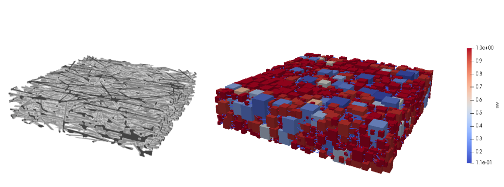
To identify the relevant interface processes, a good description of the multiphase flow in the GDL on the pore-scale is crucial. The pore network model, which was developed in Project A02, is further improved to capture the properties of flow through the hydrophobic structure including corner flow and the influence of contact angle variations. An appropriate representation of the GDL structure is achieved extracting the pore network directly from the fibrous structure using the python tool PoreSpy.With a drainage process, liquid water is pushed through the structure. The simulations show, how the liquid water invades first the large pores and throats and certain break through locations occur dependent on the applied boundary conditions.
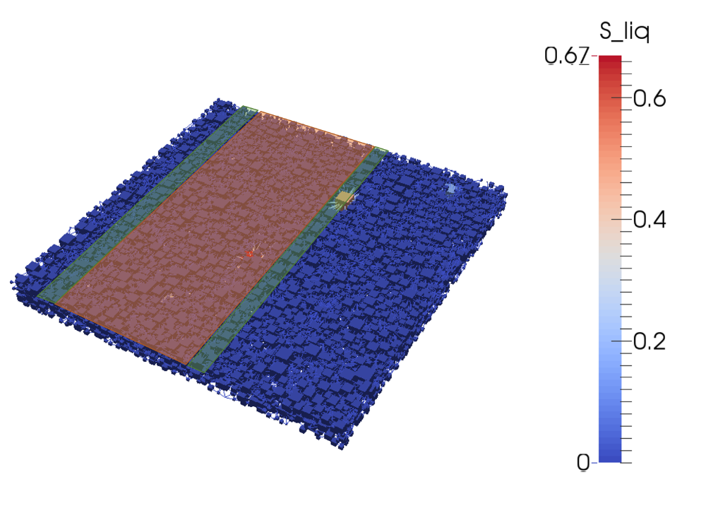
To systematically account for the challenges at the interface between GDL and gas distributor, the interface region is divided in different regions dependent on the type of interaction. In a PEM fuel cell, the GDL is partly blocked by the land parts of the gas distributor (orange area). Next to the blocked area, an interaction of the fluids within the hydrophobic GDL with the hydrophilic gas distributor surface occurs (green area). In the shown network, liquid water passes through the GDL and breaks through in the green area such that the fluid behavior is defined by the hydrophilic-hydrophobic interaction at the interface. The rest of the interface between GDL and gas distributor is in contact to the open gas channels. Here, an exchange of mass, momentum and energy between the fluids in the GDL and the gas distributor is modeled.
Contact

Rainer Helmig
Prof. Dr.-Ing. Dr.-Ing. h.c.Project Leader, Former Spokesperson, Research Projects A02, A05, and C02